When wiring a 3-phase motor, first identify the terminals U1, V1, and W1, and select the appropriate wiring method based on the motor power. For example, if using a 380V power supply, adopt the Y connection method and ensure the grounding resistance is below 4 ohms to prevent leakage.
Basics of 3-phase motor wiring
The primary way of a 3-phase motor is star connection (Y type) and delta connection (Δ type). The motor’s operating voltage and startup method are decided from these two methods. Delta connection is commonly used with the lower startup voltage and star connection with higher one. When using a 380V three-phase power supply, if the startup effect is not very ideal, we can choose the connection mode of the star-delta conversion to be connected.
Be sure to have at least a multimeter, some terminal connectors, and some electrical insulation tape before wiring the bar so you get each wire right into the correct places. One of the corresponding input and output terminals, with respect to the 3-phase motor three terminals will be marked U1, V1, W1 on a 3 phase electric motor terminal type while the other one will heal as U2, V2, W2. If the power supply and motor have the incorrect phase sequence, then the motor will reverse which can lead to equipment damage. Hence, verify the phase connection first using Multimeter to check its relationship each and it should be on step.
If there is a power motor (over 5 kilowatts) to be used, I recommend you install the contactors and thermal relays before making the connection with the motor. Not only does this improve the startup efficiency of the motor, but also prolongs the life of the motor. When installing wire must be selected according to the power of the motor, to avoid at high-power overheating or short circuit. This means a minimum of 4 square-millimeter copper wire is required for currents of about 10 amps and larger than about 7.5 kW motor.

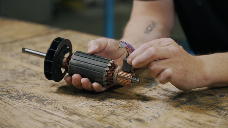
Identifying motor terminals
Know your motor terminals before wiring a 3-phase motor. In most cases the U1, V1, W1 are the input terminals of the three-phase motor that are terminal for connection to the junction box at the motor, while U2, V2, W2 as output. The input and output wire termination must be with the respective wires to its power supply or load. Don’t worry, as soon as the wiring is messed up the motor will either run backward or get ruined. An incorrect terminal connection can result in enough power exceeding 5 kilowatts for the motor to fault an electrical system, so identification is essential.
So essentially what you need to memorize is how those terminals are usually labelled If you are unsure of the two terminals, you can always run a resistance check on each terminal to the winding with a multi-meter. Generally speaking, the resistance distributions shown will be symmetrical when the appropriate wiring sequence is used. U1 and U2, V1 and V2, W1 and W2: these identities connect to both sides of the winding in a normal 3-Phase motor, with normally only a few ohms to several tens of ohms between each group of windings (depending on consumer power/winding spec.). Correct identification of these terminals will prevent equipment damage and provide maximum motor efficiency.
The 3-phase motor winding has a resistance value that is essentially identical from one winding to the other, which will determine pins U, V & W for each group of LV outlets. Another example could be when you measure resistance values of 5, 5.1 and 5 ohms; this tells you that the windings are ok (this result instead to do an exact wiring). Here is where one important feature comes in: Always check the motor nameplate data (voltage, power, etc) before the wiring so that the wiring equipment matches with the voltage written in this plate. Star (Y type) or delta (Δ type) corresponding to different power voltage levels, if the motor nameplate is marked with a number of 380V/220V, you can choose Star or Delta connection.
Difference between Y-type and Δ-type wiring
The 3-phase motor is generally wired with Y wiring and Δ wiring, and it directly affect the voltage of the operating motor and startup characteristics. Y-type connection ideal for higher voltage applications such as in 380V power circuit. If the motor windings are Y-connected, the voltage across each winding is the phase voltage and about 58% of the line voltage. Ie the motor is with nameplate of “380V/220V”, it may work at 380V.
Y type start, It is used in the low voltage applications such as 220V supply system along with the Δ type connection. Each winding will have to bear the line voltage for Δ type connection for the same motor. The advantage of this wiring is that it allows for higher starting torque which could be necessary for applications where a heavy load must be started. Take a 7.5k 3-phase motor, for example: If it is started at 380V and the load is relatively light, Y voltage can be selected to reduce the starting current and avoid excessive impact on the power grid. If the 3-phase motor needs a 220V low-voltage system, it is best for choosing Δ type connection to start with higher torque.

Grounding and safety measures
The other reason why this is important in developing the wiring — this is the grounding which also comes for protecting other equipment and even keeping users safe. Good grounding can make your motor shell equipped with a powered, to prevent leakage into the need to live touch of an electric shock accident. Larger motors or systems for industrial use control the maximum resistance to ground to be less than 4 ohms so that a small current leak that need not come back up as shock (hazard) is quickly drained away into earth.
The grounding of a 3-phased motor should comply with the industry standard IEC 60364 and other such global electrical standards. Usually the metal casing of motor is connected to ground wire, specification (capacity) of ground wire and motor power should be calibrated. If you are installing it on the 11 kilowatt machine, then the cross-sectional area of the ground wire should be larger than 10 square millimeter to ensure that in case of short circuit leakage can pass through in order to achieve timely cut off the power supply so as not to cause equipment damage or fire danger.
A further danger is that the motor casing can become live as a result of leakage or insulation breakdown. Fatal electric shock accidents can be triggered by touching a live casing in humid environments. This can be prevented by verifying the ground wire is securely connected when wiring, and keeping an eye on your grounding system. This is best for motors and any devices with a metal casing to them. It should be tested to verify that the grounding is effected before starting the motor, i.e. the grounding resistance shall be within a proper range each time when he motor is started. If there is too much grounding resistance, the protection will be affected, and it may affect the normal operation of the motor, and ultimately worsen its service life.