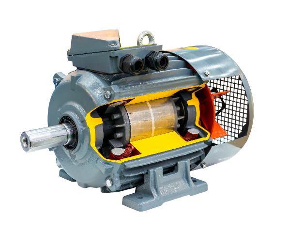
Choose a screw for grounding or a chassis point for grounding of the motor. The grounding wire should be 4-10mm² copper wire; the grounding resistance should be less than 4Ω (less than 1Ω if the ambient humidity is more than 80%). Fasten one end of the grounding wire to the motor’s grounding terminal and the other end to the equipment grounding busbar, ensuring that there is good contact and a firm connection of the grounding wire.
Preparation Work
Before the grounding work is started, a lot of preparation work must be done. The grounding is an essential part of electric engineering, which cannot be done with carelessness and must be done according to standards. The following work must be finished before the grounding is done.
Power-off confirmation: Before grounding, ensure that the relevant power supplies are disconnected and discharge electrical parts of the motor. A multimeter or test pen can be used to confirm the status of the power to ensure there is no risk of electric shock when operating. Also, hang warning signs on the motor control cabinet or distribution box to prevent others from mistakenly operating it, such as “Under Maintenance, Do Not Switch On.”
Tools and materials preparation: The major equipment used in the grounding are a screwdriver, wrench, crimper, insulated gloves, and a ground resistance tester. Usually, the grounding wire is made up of a multi-core copper conductor, and the specification should meet the requirements of the standard. For motors under 10kW, the wire can be of a cross-sectional area of 4mm²; from 10 to 50kW, it should be 6mm² or larger. In the case of larger capacity motors, a wire gauge for grounding should be selected based on the rated current of the motor.
Check the grounding device and grounding resistance: Check on-site the existing grounding device. Continuity in the grounding grid or busbar should be tested for any damage. The grounding cable should not be fractured or decayed. The grounding resistance tester shall measure the grounding resistance value within the specified requirement. Under normal conditions, the ground resistance for every standard motor shall not be more than 4Ω. Operating in humid or special environments, it shall not be over 1Ω.
Choosing the Grounding Position
The grounding work is based on the selection of the three-phase motor’s grounding position. The appropriate selection of the grounding position can ensure that the contact resistance between the grounding wire and the motor will be very small, and later maintenance and inspection will be convenient.
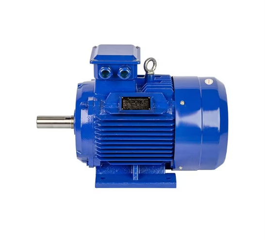
Grounding position on the motor body: Inside the enclosure or junction box of a three-phase motor, there is usually a screw or plate fixed for grounding, marked with a grounding symbol (⏚). These grounding points are usually at the bottom or on the side of the motor. The grounding wire should connect to the closest point and ensure that there is no painting or rust on the screw hole. If there is a coating, clean it so that good metal-to-metal contact is guaranteed.
Grounding at the base: If no particular screw is available on the housing for grounding, it is possible to use one of the mounting bolts of the base as a point of connection for grounding. The base surface must be cleaned and free of rust; if necessary, use sandpaper or a wire brush in order to have good electrical contact. Also, secure the grounding lug with a bolt fitted with a washer in order not to loosen due to vibration.
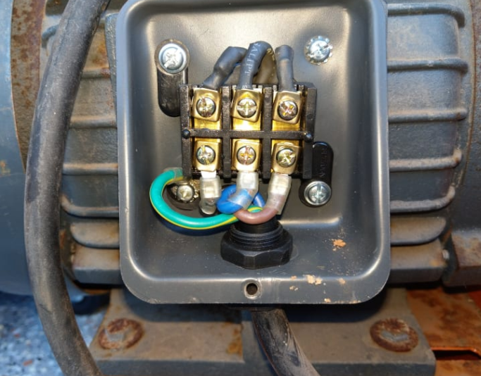
Grounding inside the junction box: There is usually a screw for grounding or a metal plate for grounding inside the junction box of the motor, to which the grounding wire can be attached. However, ensure that this type of grounding is well connected to the motor housing and consistent with the main grounding point.

Grounding Wire Connection Method
The connection method of the grounding wire directly influences the effect and safety of the grounding. In the actual project, the mechanical strength, corrosion resistance, and electrical performance of the grounding wire should meet the requirements of the standard.
Treatment of the grounding wire end: The insulation should be stripped; 10-20mm is typical, but with the copper conductor left intact before connecting to the ground wire. Crimp the terminal lug onto the copper conductor part by means of a crimping tool to avoid the core loose to a bad connection.
Fixing the grounding wire: Attach the terminal lug or the grounding ear to the grounding screw in the motor and then fix the nut. To ensure that the grounding wire does not become loose due to vibration, a locking washer or nut should be used for reinforcement. The location for installation of the grounding wire must be such that it will not have bends and loops but will follow the shortest possible route and be fixed at appropriate places. Fasten the wire around the cable tray using clips or cable ties so that it does not sag loose under its weight.
Connection to the grounding busbar: The other end of the grounding wire shall be tied to the equipment’s grounding copper bar or grounding busbar. Normally, it is housed inside the motor control cabinet or around the grounding device. The connection should use a terminal lug, too, and fasten with a bolt.
Selection of Grounding Terminals
Selection of the grounding terminal shall be based on the specific motor installation environment and equipment layout. The grounding terminal of the motor should be uniform with the grounding point of the whole system in general.
Single-point grounding: In most cases, the grounding terminal of the motor should be connected with the main grounding busbar (PE line) of the equipment or with the grounding network to achieve single-point earthing, thereby avoiding too-long loops in the ground circuit and electromagnetic interference problems.
Connection to the grounding busbar: The grounding busbar is usually at the bottom of the distribution or control cabinet and is of a thick copper bar. In turn, the wire for grounding must be connected directly to it and strongly screwed with a dedicated bolt. The torque cannot be too strong to damage the grounding wire or busbar.
Handling multi-point grounding: If there are many pieces of equipment or the equipment is spread over a large area, multi-point grounding can be performed. However, ensure that all grounding terminals are ultimately connected to the grounding busbar or network and that the grounding resistance in the ground is at a standard requirement.
Ensuring Proper Grounding
Inspections and tests shall be performed after the grounding is done to make sure proper ground resistance is achieved, which needs to be within the requirements and to make sure that the grounding system does not pose any hazard.
Ground resistance testing: The resistance between the motor’s grounding terminal and the earth shall be measured using a ground resistance tester or megger. Generally speaking, the grounding resistance shall be less than 4Ω for a general industrial work site and less than 1Ω for a motor running under damp and corrosive conditions. Large resistance is generally caused by poor connecting of the earthing wire, corrosion of the earthing network, or poor contact with the earthing electrode. Timely inspection and handling are needed.
Mechanical strength testing: After connecting the grounding wire, softly pull the wire to check whether the terminal is loose or detached. The grounding wire should possess enough mechanical strength and can’t be looser under equipment vibration or external force.
Electrical performance testing: Whether or not the resistance value of the grounding wire achieves 0Ω while the multimeter is in a measuring state checks whether the insulation of the motor and the grounding system is normal.

Precautions
Many details need attention during grounding, and negligence can lead to grounding failure or electrical faults.
Grounding wire cross-sectional area selection: The cross-sectional area of the grounding wire should meet the needs of the current, usually selected to be at least half of the cross-sectional area of the phase wire. Such as the rated current of the motor is 50A, the grounding wire can use a wire with a 10mm² cross-sectional area.
Laying method of grounding wire: The grounding wire should be laid as straight as possible with minimal bends, preventing the coiling around or entanglement of other cables. The laying of a grounding wire should be separated from that of high-power cables to avoid electromagnetic induction interference.
Separation of grounding and neutral wires: The neutral wire and grounding wire should be laid strictly separately in the grounding system to avoid leakage or reverse current flow when there is a fault.
Regular inspection and maintenance: The grounding wire and terminal have to be inspected on a regular basis, especially in those who work outdoors or under moist conditions where corrosion and loosening are likely to happen. The grounding systems that have been used for a pretty long time are recommended to conduct a comprehensive check every six months to a year.
Types of Grounding Systems
The types of grounding systems refer to the different methods of grounding applied to electrical systems. The following are the common types used for three-phase motors.
TN system (TN-S/TN-C): TN system is the most common grounding method applied. The TN system has been divided into TN-S and TN-C. In TN-S, the laying of the grounding wire PE and neutral wire N are separately laid, and it is applicable for large-current equipment. In the TN-C system, the grounding and neutral wires are combined and used in small-power equipment.
TT system: Within the system, the equipment grounding is independent of the power system grounding point and normally uses an independent grounding electrode. Thus, this system is appropriate for an installation where the power system grounding point cannot be introduced conveniently into the equipment but requires lower ground resistance.
IT system: In the IT system, the neutral point of a power system is not grounded or is grounded through high impedance. It is usually utilized for critical equipment or special occasions such as hospitals and data centers, etc. It can effectively avoid the influence brought about by a single-phase ground fault in the system.
