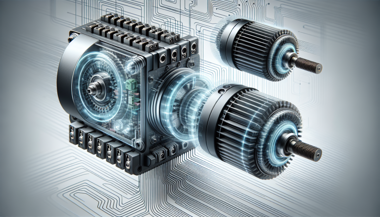
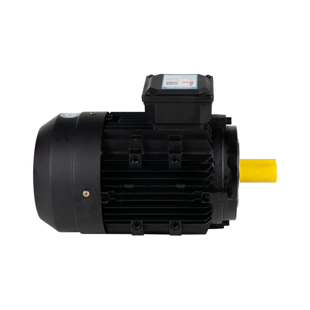
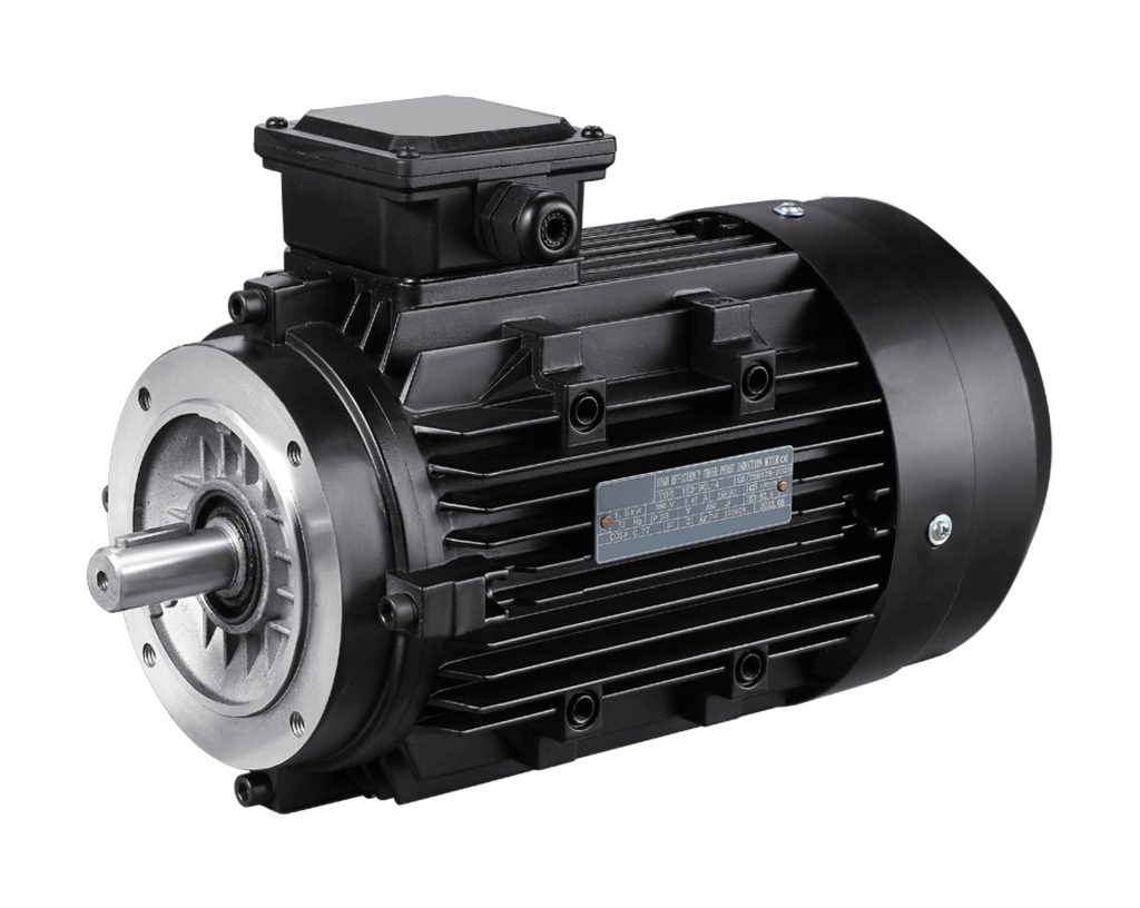
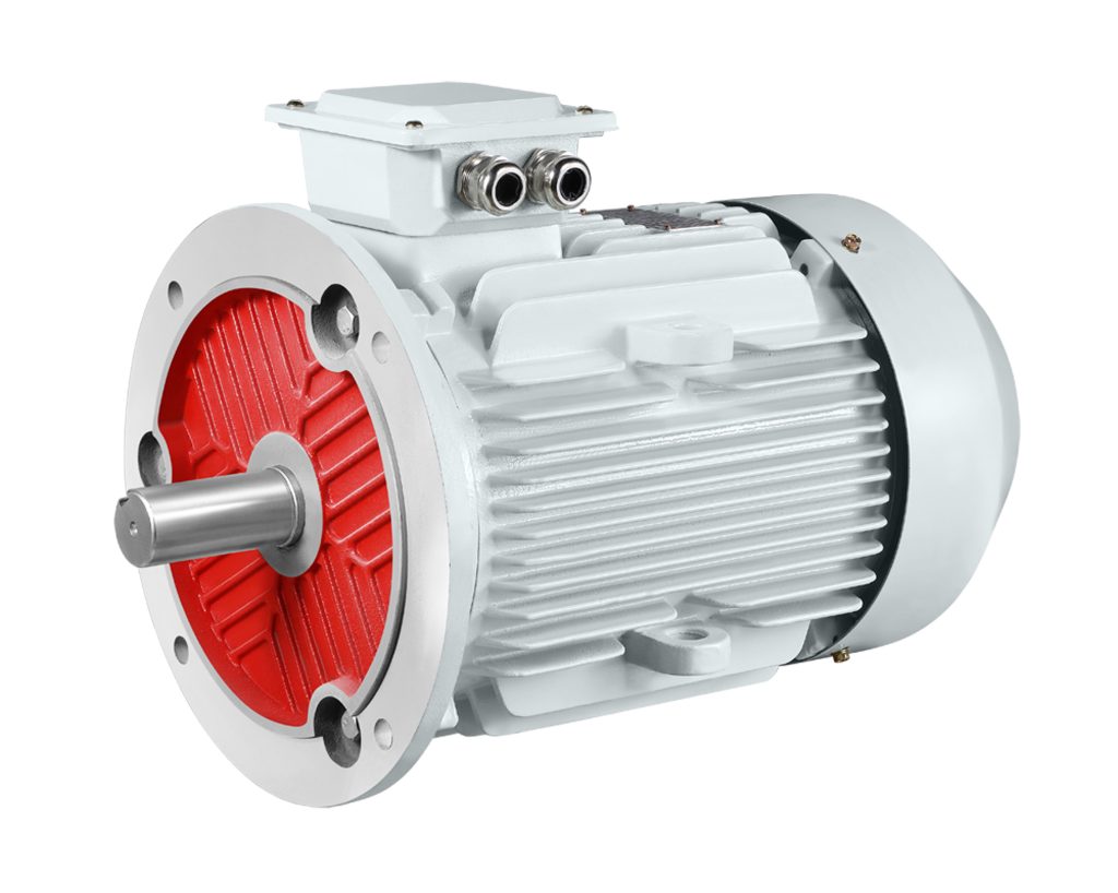
A three-phase induction motor works on the principle of an alternating current instead of direct current. It requires a three-phase AC power supply for creating a rotating magnetic field in the stator windings capable of turning the rotor. This is because the three-phase power supply consists of three ACs, all having a phase difference of 120 degrees, and hence the motor is capable of providing smooth and constant torque. Thus, it has an application in driving heavy loads and industrial equipment such as pumps, fans, and compressors. However, proper wiring and ensuring the power frequency matches the motor specification is one of the important steps for its running.
Table of Contents
ToggleAC Basics
This three-phase induction motor needs AC power to operate—which is also one of the very widespread sources of energy in industry. The nature of AC is such that voltage and current are periodically varied with time, normally in the form of a sine wave. In industry, the three-phase power is normative, where there are three current lines, 120-degree out-of-phase each, balancing each other out to create a continuous and stable electromagnetic force. It is a balanced power structure that will prevent harmonic distortion and improve the power factor while reducing losses during the transmission of power.
Power grid frequencies are also different in different parts of the globe. Examples are 60 Hz in North America and some Asian countries, and 50 Hz in Europe and most other countries. Three-phase power has high power density and stability, used in the feeding of heavy-duty equipment such as industrial pumps, compressors, and fans.
One of the key benefits for AC systems is the ease with which voltage transformation can be achieved. With the aid of transformers, AC voltage can easily be transformed upward or downward, a process utilized to great advantage in long-distance power transmission. The power companies transmit electricity at high voltages and then reduce the voltage at the site of consumption to safely supply the various equipment. These three-phase induction motors draw great benefits from this since they receive stable and robust power.
Motor Types
In respect to the rotor construction, the three-phase induction motors can be categorized into two groups: the squirrel cage induction motors and the wound rotor induction motors.
Squirrel Cage Induction Motor
In fact, more than 90% share of the total induction motor market is consumed by squirrel cage induction motors. The main structure includes the squirrel cage rotor, which is made of copper or aluminum bars connected by two end rings, forming a closed loop resembling a squirrel cage. A rotor of such design is simple and tough, highly reliable, and withstands impacts of frequent starts and heavy loads.
Being slip ring and brush-free, such motors can be considered practically maintenance-free, highly reliable, and inexpensive. Squirrel cage motors find application in all equipment requiring operation on a continuous basis; for example, fans, pumps, conveyors, and compressors share the advantages of mechanical strength and long life with the industrial user. In recent years, efficient squirrel cage motor technology has improved because of better materials and production techniques. It is very helpful in improving efficiency and reducing losses.
Wound Rotor Induction Motor
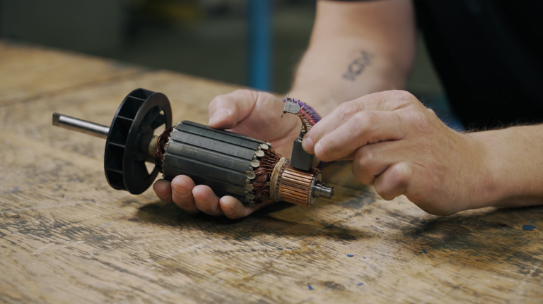
Rotor windings of the wound rotor induction motor resemble those of the stator and are connected to an external circuit by means of slip rings and brushes. Adjustable external resistors may be provided for starting current and torque control in high torque applications such as cranes, hoists, and large fans. Inasmuch as the design is more complicated, wound rotor motors have the advantage of giving accurate speed and load control with dynamic requirements in the environment.
Due to the wear of constituents, the slip ring system of the wound rotor motor requires maintenance periodically. Even with this disadvantage, however, the motor is indispensable for applications such as mine ventilation systems and boiler feed pumps at power stations.

How It Works
The working principle of three-phase induction motors depends on electromagnetic induction and RMF. Since three-phase AC is applied to the stator windings, a rotating magnetic field arises in the stator core. The angular speed, dependent upon supply frequency and the number of poles, interacts with the rotor. While intercepting the magnetic flux, the rotor conductors induce a current due to electromagnetic induction. These induced currents act together with the rotating magnetic field to generate electromagnetic torque that acts to drive the rotor.
The rotor is never at the synchronous speed of the magnetic field—through which the induced currents and torque would cease to exist—and this causes a so-called slip. Slip describes the difference between synchronous speed and actual rotor speed and is a key quantity for torque generation: for light loads, it is small; it increases strongly for heavy loads.
Without a mechanical commutator and brushes, friction loss is negligible, reducing the maintenance requirement: the induction motor is very reliable and its lifespan is considerably prolonged. The induction motor was most suitable for industrial use in every field, especially under the worst conditions of such industries as petrochemical plants and mining.
AC vs. DC
The principal difference between AC and DC is that the former periodically reverses direction, while the latter always flows in one direction. DC motors generally use a commutator and brushes to control current direction, creating friction that increases their wear and, therefore, maintenance requirements.
DC motors find application in special uses requiring high starting torque and precise speed control, such as electric vehicles and industrial servos. However, their design is more complicated than that of three-phase induction motors, and the manufacturing and maintenance costs are higher. Nowadays, because of the higher reliability and lower maintenance demands, AC motors dominate in modern industrial systems.
The application possibility of AC induction motors has been increased due to the recent development of VFD technology. VFDs change the input frequency to provide high accuracy in speed control, soft-starting, and high system efficiency. Utilizing VFDs within AC motor systems can save up to 20-30% of energy consumption, which is very important for industrial energy saving.
Whereas DC motors find applications in cases requiring precision control, the development of power electronics and control technologies is continuously pushing the application boundaries of AC motors.
Core Parts
Major components making up a three-phase induction motor are: stator, rotor, bearings, cooling system.
Stator
The stator is the stationary part of the motor, typically made from high-magnetic-permeability silicon steel sheets, often stacked to minimize iron losses. The stator windings are of insulated copper wire that should be capable of withstanding high currents and temperatures. The stator core slots will directly affect the performance of any motor; thus, optimized slots will reduce eddy current losses and magnetic leakage, hence raising the efficiency.
Energized, stator windings will develop a rotating magnetic field in which the motor will operate continuously. In high-efficiency motors, the core materials are of lower losses, and insulation designs further contribute to economy in energy consumption. For some industrial applications, the motor standards call for protection features like dust and water resistance to operate in harsh conditions.
Rotor
The rotor is the rotating part of the motor and is mainly classified into squirrel cage and wound types. The rotor in the squirrel cage makes use of copper or aluminum bars connected by end rings to form a closed circuit. Qualitative rotors are made through casting or pressure die-casting for great mechanical strength and conductivity.
The slip rings connect the windings of a wound rotor to an external circuit to permit changing the resistance for handling different starting characteristics and torques. For this reason, wound rotors are applicable particularly in heavy-duty lifting equipment or large mills.
Bearings
These are supported by bearings that reduce rotational friction, and normally ball or sleeve bearings are used. The design of the bearing system directly influences motor life and performance. Precision bearings are used for high-load applications to minimize mechanical losses, which should be regularly lubricated to sustain performance. Most motor failures occur due to bearing failures, and hence periodic inspection and maintenance are required.
Cooling System
Operating three-phase induction motors, particularly on heavy loads or for long periods, tend to heat up considerably. Cooling systems are usually done with fans for dissipating heat or liquid cooling mechanisms for big industrial motors for effectiveness. A few motors are designed to contain thermal protection devices that automatically shut off power when the temperature rises beyond safe levels and may cause the motor to burn out.

Power Supply
Three-phase induction motors need three-phase AC power supplies. Motors, depending on the method of connection, can use either a star (Y) or delta connection. In the case of high-voltage motors, to reduce stress on windings, the star connection is used. Whereas, for low-voltage, high-current applications, delta connection is done. Design choice affects starting current, efficiency, and torque output characteristics.
These VFDs have become a must in modern industries because it gives an exact control on speed and power input by changing the supply frequency. This will result in improved motor efficiency, reduced impact on the power grid due to starting current, and reduced wear and tear of equipment. In industrial automation, demand for VFD has increased manifold, especially where dynamic changes in loads are being encountered.
The VFDs also boast a regenerative capability that allows them to feed energy back into the power grid, further improving overall system efficiency. This feature is of paramount importance for energy management in applications involving lots of acceleration and deceleration.
Common Uses
Their applications are very widespread in industry, commerce, and in infrastructure projects. In manufacturing, three-phase induction motors drive heavy machinery like lathes, milling machines, and presses, as well as automated assembly lines. High reliability and powerful performance are ensured for construction cranes and large elevators. In applications pertaining to mining and petrochemicals, induction motors drive conveyor belts, drilling rigs, and pumps with unfailing operation amidst dust and humidity.
Induction motors drive the fans and pumps for cooling towers in HVAC systems used in regulating indoor air temperature and quality. Besides that, it has been estimated that HVAC systems, which operate in shopping malls and office buildings, account for more than 40% of the energy consumption that could be drastically reduced by optimizing their motor operations.
Water treatment plants use induction motors for driving big centrifugal pumps in sewage processing and clean water distribution to ensure stability and efficiency of urban water supplies. In agriculture, the induction motors are used in irrigation systems for pumping and distributing water, especially in long-duration continuous operation applications. The high reliability and low maintenance of these motors make them the preferred choice to ensure smooth agricultural production.
