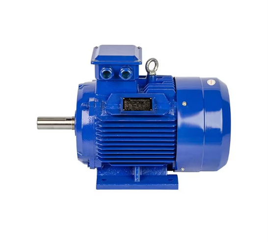
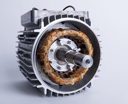
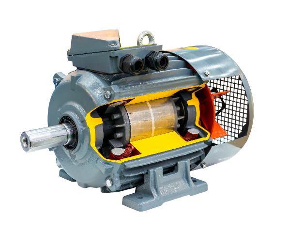
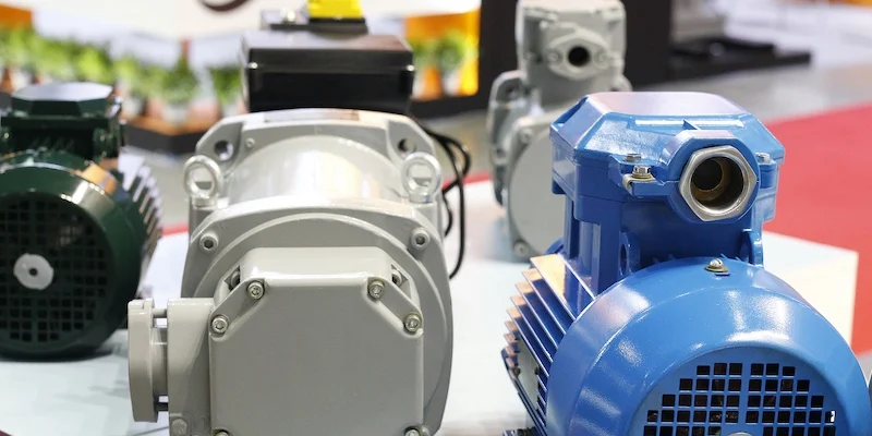
The basic components comprising a three-phase induction motor are the stator, rotor, windings, power input, bearings, and cooling system. The stator provides a rotating magnetic field through the windings, the rotor rotates under the influence of the magnetic field, bearings support the rotation, and the cooling system prevents overheating.
Stator Basics
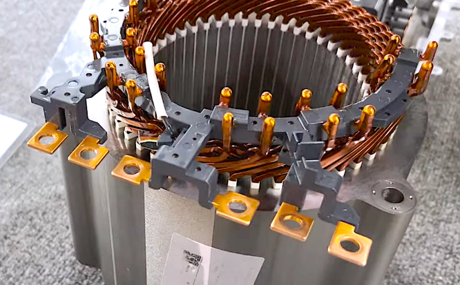
In the three-phase motor, the stator is the stationary part, and the major role it plays is to provide a rotating magnetic field that will drive the rotation of the rotor. The stator is comprised of a core and windings. The core normally makes a use of high magnetic permeability laminated silicon steel sheets that will effectively reduce the hysteresis losses. The usual thickness of the sheets is 0.35mm or 0.5mm, depending on the operating frequency of the motor. The thinner the sheet less eddy current loss, but relatively higher will be the cost of manufacturing. So, a compromise must be reached between efficiency and cost.
The windings are the most important part of the motor as it is responsible for converting the electrical energy into magnetic energy. In three-phase motors, there are windings for three-phase AC power supply. Each phase is separately wound and placed such that there is a phase difference of 120 degrees between them. This allows the generation of a rotating magnetic field when three-phase voltage is applied inside the windings. Materials of Windings Common materials employed for winding purposes are copper and aluminum. Copper, with its very low resistivity and outstanding conductivity, finds extensive applications in high-efficiency motors. Compared to copper, aluminum is less conductive but much cheaper and lighter; hence, it also finds applications in some low-cost motors.
Another factor considered in designing the stator will be the heat dissipation. During long operation of the motor, heat generated from windings and core accumulates to raise the temperature of the motor. Therefore, besides which stator is mostly designed with cooling channels to avoid overheating, external air or water cooling systems may also be fitted to cool the stator so as to ensure that the motor can work in an appropriate temperature while providing good efficiency. Therefore, the cooling performance of the stator directly influences the lifetime of the motor and operational efficiency; cleaning the cooling channel is thus a critical step of regular maintenance.
Rotor Types
The rotor of the three-phase motor moves with the rotating magnetic field and converts the electromagnetic energy into mechanical energy within the motor. Based on the structure of the rotor, the three-phase motors are primarily classified into two types: squirrel-cage rotors and wound rotors.
Due to the simple and rugged construction, a squirrel-cage rotor is finding very wide applications in industrial and household motors. It comprises a set of copper or aluminum bars, which, when shorted at both ends by copper or aluminum rings, form a cage-like structure, resembling that of a “squirrel cage.” The current in the bars is induced the moment the rotor bars cut through the rotating magnetic field generated by the stator. By the law of electromagnetic induction, the induced current forms an electromagnetic force in the rotor and drives the rotor to follow the rotating magnetic field of the stator. Because the squirrel cage rotor has many favorable features such as simple structure, easy fabrication, and low cost, it gives relatively small starting torque.
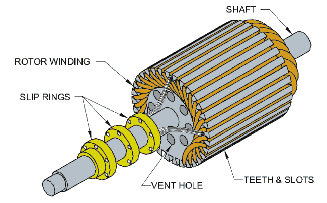
The wound rotor itself has a more complex design, carrying windings similar to the stator windings-wound usually with copper wire. In each phase of the wound rotor windings, external resistance can adjust slip rings and brushes to change the starting current and torque. It follows that such a structure will provide higher starting torque and lower starting current in the process of starting. Wound rotors serve usually in places that require frequent starts and stops with bigger loads, such as in cranes, big pumps, and wind power equipment.
The advantage of the wound rotor is that starting and running performance can be flexibly controlled by changing the values of the external resistors. Because of the complicated structure and higher service cost, this type of motor serves only in certain industrial areas.
Power Supply
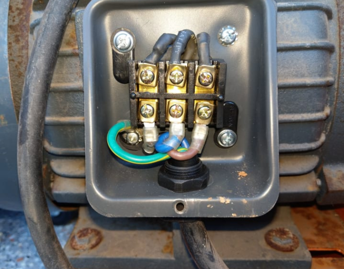
In three-phase motors, the power in the three-phase AC supplies, where the specification and quality of the power directly influence the performance of the motor. In a three-phase AC, there is a phase difference of 120 degrees between every phase. Passing this three-phase through the three-phase windings creates a continuous, uniform rotating magnetic field. Therefore, generally speaking, three-phase motors are more efficient than single-phase motors. The common three-phase voltage level in the system can be 380V, 400V, and 415V; the frequency is generally set to 50Hz or 60Hz depending on the region and the standard on the power grid.
Among the determining factors of the speed of the motor is the supply frequency. The power supply frequency and pole number can be described by formula n = 120f/p, which decides the theoretical speed of the motor. Changing the power supply frequency can change the speed of the motor. This is the basic principle of the variable frequency speed regulation. Frequency converters are widely used in industrial applications to set the operating speed of motors accurately, according to working conditions and in order to save energy. Voltage fluctuations in the power can also have much consequences on the motor itself: if the voltage is too high, overheating of the windings might occur and with such high voltage damage to the insulation is possible; if the voltage is too low, then the torque developed within the motor will be too low and that might easily lead to overload conditions. Especially under heavy-load and continuous operation conditions, there are higher demands for a stable power supply. In order to prevent failures caused by abnormal power supply, many motor systems have protection devices in their voltages to make sure the operating voltage of the motor falls within the range of safety. This ensures that no damage will come to the motor.
Windings Role
Windings are considered important components in a three-phase motor, which convert electrical energy to electromagnetic energy to further rotate the rotor via electromagnetic interaction. In general, the stator windings of the motor may be made of copper or aluminum wires. The sets of windings are connected to the three live wires of a three-phase AC power supply and are further spatially offset from each other by 120 degrees. Due to the alternating current provided by the three-phase power source, the windings have a time and space phase difference, thereby creating a stable rotating magnetic field.
The number of turns of windings and their design determines the main parameters of the motor. In the case of more turns, the higher value of the induced electromotive force is very often accompanied by higher resistance and inductance of windings, which results in higher losses of energy. That is why the number of turns and wire gauge in the designed winding should be carefully selected by the engineer with respect to the specific application and motor specification in order to balance efficiency, output power, and cost.
The materials of the windings also have a very direct influence on the motor performance. Since copper has very low resistivity and is a very good conductor, most high-efficiency motors make use of copper winding. As copper is very expensive, some low-cost motors employ aluminum windings. Since aluminum has much higher resistivity compared to copper, motors with aluminum windings need thicker wires to achieve the same level of efficiency.
The connection of the windings themselves can also be adapted for different operating characteristics in a motor. The stator windings can usually be connected in either “star” or “delta” arrangements. Star connection has the advantage of low starting current and thus suits light-load start applications, while delta connection provides higher torque at start-up, suitable for heavy-load start conditions. In some complex applications, motors adopt dual-speed or multi-speed winding designs, and by changing the different winding connections, different speed requirements can be achieved.

Magnetic Field Principle
The operating principle of a three-phase induction motor mainly depends on the interaction of electromagnetic induction with the rotating magnetic field. When three-phase current flows through the stator windings, there is development of a continuous rotating magnetic field inside the stator. The developed rotating magnetic field and the relative motion between rotor create an induced current in the rotor bars. According to the law of electromagnetic induction, the induced current forms an electromagnetic force on the rotor, and the rotor starts following the movement of the rotating magnetic field.
The synchronous speed of the motor depends on the frequency of power supply and the number of poles inside a motor, and theoretical speed can be calculated with the formula n = 120f / p. However, the real operational speed of the motor is always somewhat smaller than the synchronous one; this is called “slip.” It is possible to find the slip rate with the formula s = (ns – n) / ns, where ns is the synchronous speed, and n is the real current speed. Slip rate generally lies between 2% to 5%. Hence, it can be concluded that the real speed of the motor is always less than the theoretical synchronous speed.
The strength of the magnetic field has a great effect on the efficiency and output power of the motor. Larger the magnetic flux density, higher is the output power and the efficiency of the motor. However, excessively large magnetic flux density will cause magnetic saturation, which increases the hysteresis and eddy current losses of the core. Therefore, to realize the highest efficiency in energy conversion in motor design, the value of the magnetic flux density and magnetic field strength should be calculated precisely.
Cooling System
A three-phase motor develops considerable heat during operation, particularly if the load applied is large and continuous. The heating will cause ageing of the insulation of the windings, damage to the bearing, and distortion of the rotor. In this aspect, to prevent the failure of an engine due to high temperatures, cooling methods become an important factor in the design of a motor.
There exists several methods for cooling motors. Some of them are air cooling and water cooling systems. Air cooling depends upon an external fan mounted on the motor to draw air through the motor. The air carries away the heat generated by the windings and core. Since this cooling method is so simple and inexpensive, it finds very wide application on small and medium-sized motors. Large motors, however, or even fairly small ones operated in especially high-temperature ambient environments will not be sufficiently served by air cooling. In water cooling, however, coolant-young usually consists of water or oil-is circulated through the motor’s cooling channels to effectively take out the heat inside the motor. Water cooling is normally more effective than air cooling in cooling efficiency and, hence, becomes effective in high-power or high-efficiency applications of a motor.
Some high-efficiency energy-saving motors use advanced cooling technologies such as liquid metal cooling or heat pipe cooling systems. Although these are much more expensive, they can effectively improve the cooling efficiency of the motor, extend equipment life, and reduce energy consumption in the case of long-term operation.
Common Issues
In actual use, many different kinds of faults and problems may be met by the three-phase motors. The common ones are the short circuit of the windings, breakage of rotor bars, power supply voltage fluctuation, and bearing failure. The winding short circuiting is generally caused by ageing of insulation materials or local overheating, and the resistance of the windings is lowered and current increased, which may eventually burn down the motor.
The most common fault in the squirrel cage rotor is the break of rotor bars. After the breaking of the bars, further operation becomes unstable and vibrating with a loss of efficiency. Sometimes the motor refuses to start or operate properly. On the other hand, during high-speed rotation, the rotor will face large mechanical and electromagnetic stress; long time running with high load may result in rotor deformation or mechanical failure.
The large fluctuation in power supply voltage also has a greater impact on the normal operation of the motor. When the voltage is too low, the output torque of the motor cannot meet the requirements, which creates an overload condition; when the voltage is too high, the overheating of the windings can lead to damage of the insulation layer. For the prevention of these issues, it is recommended to install voltage protection devices in motor systems so that the motor operates within the appropriate voltage range.
Other common cases are bearing failure. The bearings of a motor wear out, after some time, due to the quality of the bearings or due to insufficient lubrication, intrusion of dust inside, etc. Usually, bearing failure is manifested by abnormal noise, increased vibration, and overheating during the operation of the motor. It is recommended to extend the service life by regular inspection and replacement of bearings, as well as ensuring good lubrication.
The basic ways of avoiding motor failure include regular maintenance and checks. Other than bearing maintenance, the most important tests are checking winding insulation resistance, cleaning of the cooling system, and overall vibration and noise of the motor.
