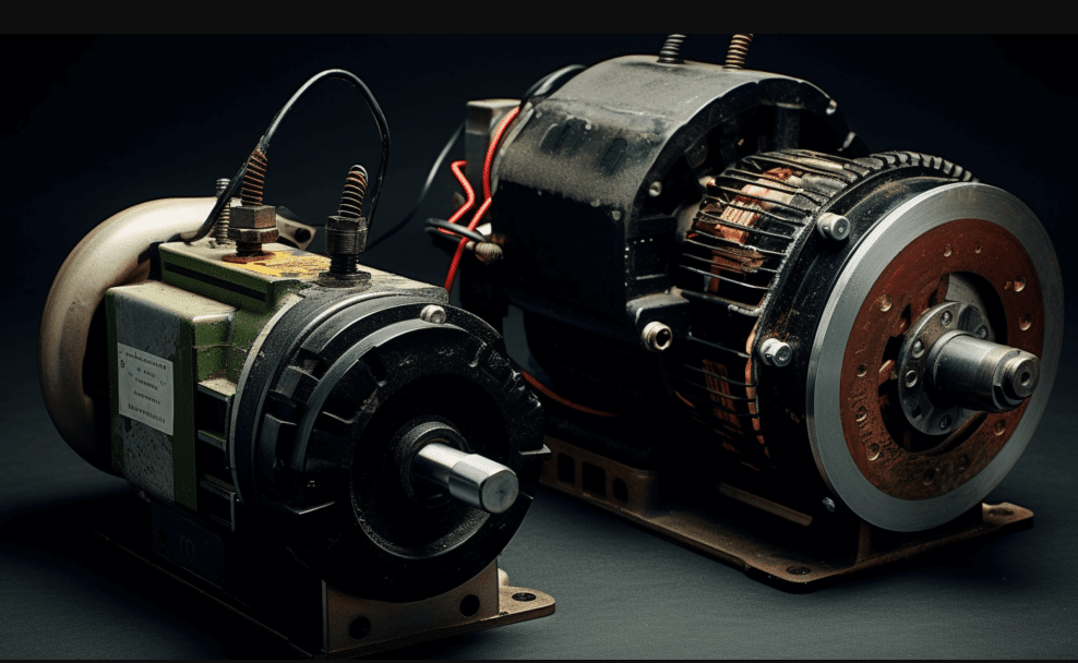
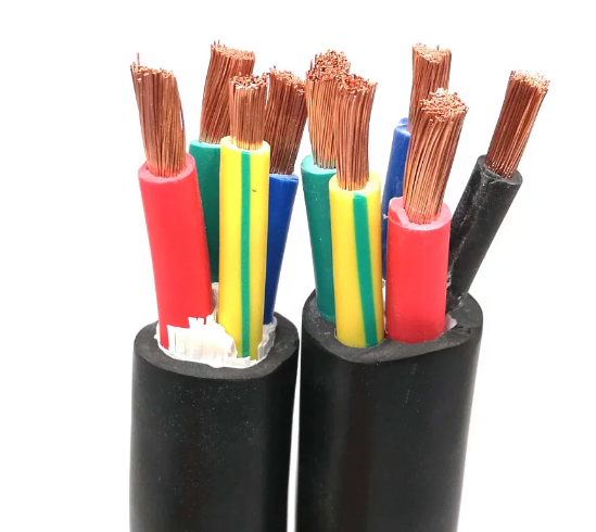
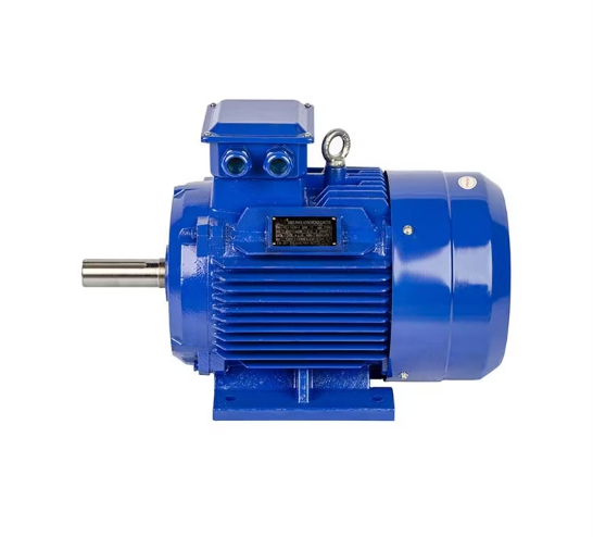
A DC motor is a device that converts direct current electrical energy into mechanical energy, driving the rotor winding through brushes to interact with the stator magnetic field, producing torque for continuous rotation. Adjusting the input voltage or using PWM control allows precise speed and torque adjustment.
What is a DC Motor
A DC motor is a converting device that transforms direct current electrical energy into mechanical energy through its working process to achieve efficient electromagnetic energy conversion. Its core mechanism mainly utilizes the force effect of a current-carrying coil in a magnetic field to transform the input DC electrical energy into rotational mechanical energy output. Such a motor offers a relatively simple structure and enables accurate control over speed and torque.
DC motors are widely used in industrial automation, transportation, and robotics. Due to the control flexibility and operational stability of DC motors, they can perform satisfactorily in most complex working conditions. Especially during frequent starting and stopping or high-precision speed-control circumstances, brushed DC motors with mature design and low cost come as the first choice for many devices.
Brushed DC motors have been widely used for their reliability of operation and the simplicity of the structure. Although brushless motor technology developed rapidly in the past several years, brushed DC motors are still occupying an important position in lots of traditional applications, especially in small and medium power drive applications.
Structural Composition
A brushed DC motor’s structure mainly consists of four core components, each playing an important role in motor operation.
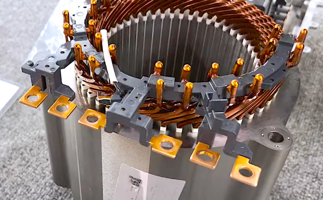
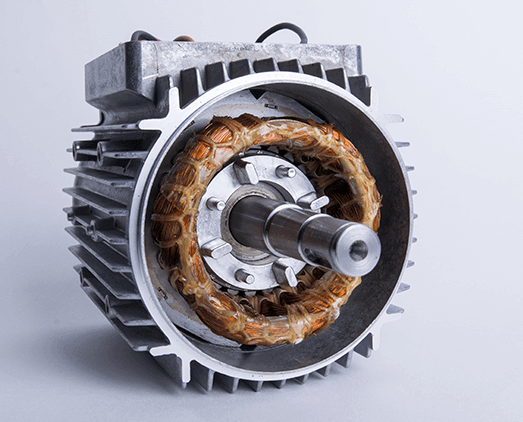
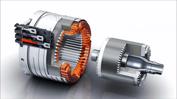
Stator: The stator is the stationary part that generates the magnetic field, creating constant magnetic fields necessary for motor operation. Common stators comprise permanent magnets or field windings. Permanent magnet stators have a simple structure and maintain a stable magnetic field, whereas field winding stators can flexibly alter magnetic field strength as a function of the excitation current. To ensure the best operating efficiency, motor stator magnetic field design is critical since it impacts the stability of torque output and overall performance.
Rotor: The rotor is the rotating part of the motor, mainly composed of winding coils and an iron core. The winding of the rotor interacts with the stator magnetic field under the influence of current to generate electromagnetic torque to drive rotational motion. The function of the iron core is to concentrate magnetic flux and thus enhance the electromagnetic effect. The design of the rotor is required to be highly precise and balanced to prevent vibrations and noise during operation.
Commutator: The commutator is a mechanical commutation device composed of numerous copper segments mounted on the rotor’s shaft end. Its function is to transfer external current through contact with the brush into the rotor winding and dynamically change the direction of current flow during rotor rotation to ensure continuous rotor rotation. The design and machining precision of the commutator directly influence the efficiency and the service life of the motor; it is, therefore, an integral component in all brushed motors.
Brush: The brush is a conductive device in contact with the commutator, typically made of carbon material. It is used to distribute electrical energy into the commutator and rotor windings. Because brushes operate in friction with the commutator face, generating wear and sparks during operation, their quality and condition necessarily need regular monitoring and maintenance.
Working Principle
The fundamental working principle of the brushed DC motor is based on electromagnetic induction and Ampere’s law. Current entering the motor is delivered through the brushes and leads through the commutator to the windings of the rotor. Electromagnetic torque for the rotor’s rotation is developed from the interaction between the current in the winding and the magnetic field produced by the stator. The commutator, meanwhile, dynamically changes the current direction with mechanical rotation and thus provides stable continuous rotation of the rotor.
The brush and commutator play central roles in motor operation. The brush transmits current to the commutator, while the commutator ensures that the direction of the current changes dynamically following rotor movement. This kind of design allows a brushed DC motor to stay efficient throughout a wide range of loads.
The entire energy conversion process begins as DC power input, which flows through the brush, commutator, and rotor windings, eventually transferring mechanical energy to the load device. Being stable and easy to use, such a motor is more adaptable for use in complex working environments.
Electromagnetic Principle Analysis
The electromagnetic basis for the operation of the brushed DC motor is the force acting on a conductor that carries current in a magnetic field. In the case of the brushed DC motor, the current in the rotor windings interacts with the stator magnetic field to generate torque responsible for the rotation of the rotor. The poles’ magnetic field is thus concentrated and distributed through pole shoes to ensure that the rotor experiences uniform electromagnetic force as it rotates.
The commutator, through its mechanical contact function, adjusts the current direction following the rotation of the rotor and prevents reversal of torque direction. Because of the coordinated operation of the commutator and brush, a brushed DC motor can continuously obtain stable rotational torque.
Besides this, the design of the rotor’s iron core plays an important role in improving electromagnetic efficiency. The iron core can reduce eddy current losses and augment the magnetic flux density, which improves the motor’s overall performance.
Types and Features
Brushed DC motors are classified into three types based on the connection of windings: series-wound motors, shunt-wound motors, and compound-wound motors.
Series-Wound Motor: In this scheme, the rotor and stator windings have a common current. The design offers a considerably high starting torque, therefore, it is applicable in equipment that requires high torque at startup, like electric vehicles and cranes. It has considerable speed regulation with load, and under no-load conditions it can have a “runaway.”
Shunt-Wound Motor: This stator winding is connected in parallel with the rotor winding, allowing the independent regulation of current. Due to relatively stable running speed, it bears less effect caused by load change, thus finding its applications in precision control equipment and industrial automation scenarios.
Compound-Wound Motor: Combining both the features of series and shunt motors, it has a constructional feature having both windings series and shunt. It has excellent starting torque and stable running under various unstable loads, thereby being widely applied in complex industrial applications.

Drive and Control Technology
Brushed DC motors rely mainly on the regulation of voltage and current. In the traditional method, the input voltage is varied to adjust speed and torque, but this shows important energy losses and range limitations in adjusting speed and torque values. Modern control technologies take on an increasing trend to high-frequency pulse-width modulation of motor input power, where the current is switched on and off rapidly, allowing efficient adjustment of speed and low-energy operating mode.
For high-precision applications, a closed-loop control system is often used in conjunction with the motor. Using speed feedback devices such as Hall sensors or optical encoders, the motor’s rotational speed may be monitored in real-time. Feedback signals to the controller are used to dynamically regulate the input current using PID control algorithms, giving the motor precise control of speed and torque.
Brushed DC motor drive systems can easily be integrated into automation control platforms, such as PLCs and microcontrollers, in modern industrial applications, further upgrading the intelligent control functions of the motor.
Common Maintenance Tips
Maintenance of brushed DC motors emphasizes the brush, commutator, and windings. Brushes are wearing parts and should be checked for length and wear. Worn-out brushes should be changed so that the machine does not operate with poor electric contact, leading to operational failure. Cleaning carbon powder and grease from the commutator surface and light sanding with fine-grit sandpaper is an effective method to enhance the motor’s conductivity.
Such a commutator, even after some time, loses its smooth surface due to friction and adversely affects operational efficiency. Maintenance of the commutator regularly reduces electrical sparking and energy loss and ensures an increase in motor life.
Another maintenance concentration is the insulation performance of rotor and stator windings. Testing the resistance of the windings regularly can check whether their insulation resistance falls within the normal range, thus preventing short circuits and overheating problems. In addition, cleanliness inside the motor by removing dust and debris, and also good ventilation, helps reduce temperature rise and enhances long-term stable operation of the motor.
