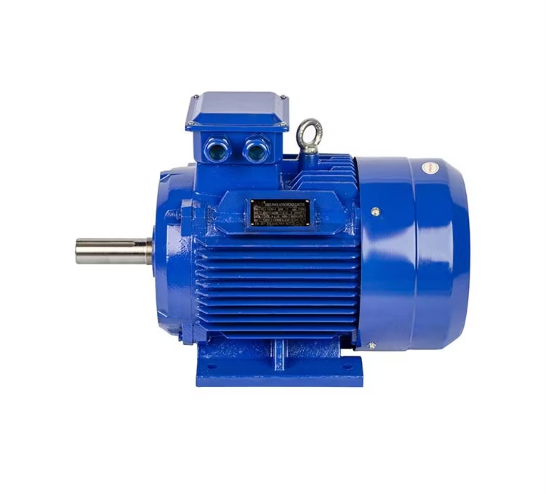
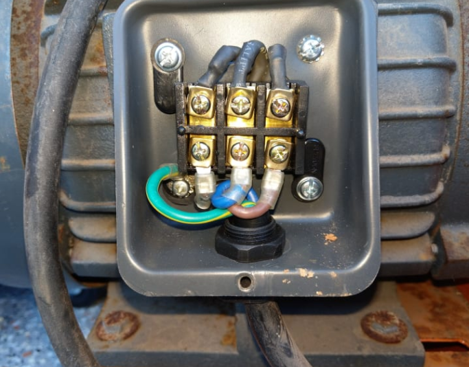
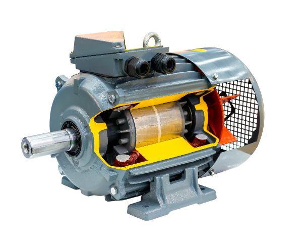
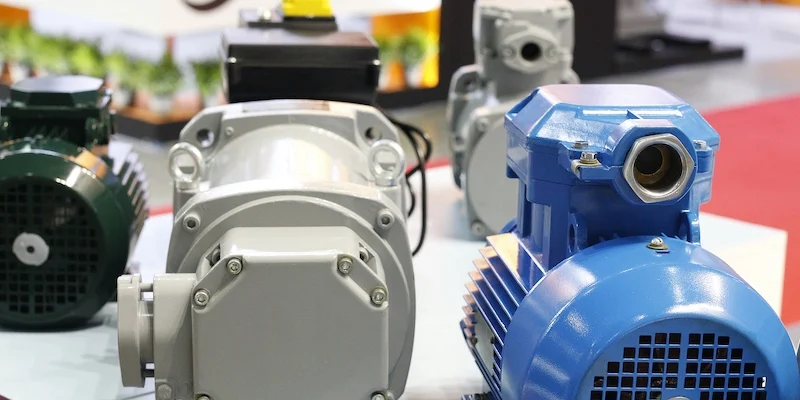
In a three-phase motor, the rotor interacts with the rotating magnetic field of the stator to convert electrical energy into mechanical energy, thereby driving the load. If the rotor overheats or vibrates, you can check the load, lubricate the bearings, and regularly clean to ensure proper cooling.
Rotor Basics
The rotor is one of the core ingredients in a three-phase motor. It functions to convert electrical energy to mechanical energy and, therefore, acts to drive mechanical equipment. The rotor interacts with the stator through the conversion of magnetic fields and electric currents to achieve the motor’s rotation. The stator usually generates a rotating magnetic field inside the motor, while the rotor starts to rotate under the action of this magnetic field, ultimately driving the output shaft of the motor. The operating principle based on this interaction enables the motor to efficiently convert energy.
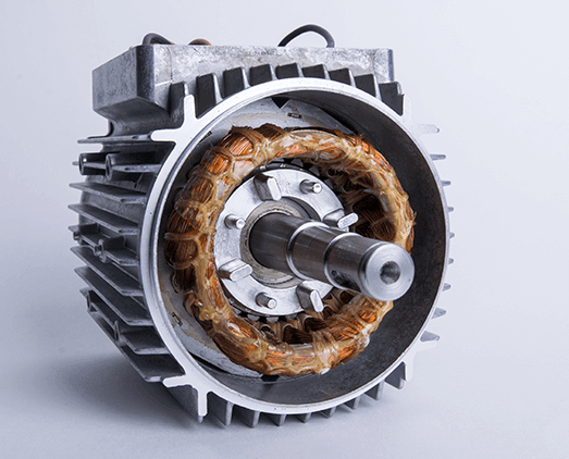
The simple structure of the rotor mainly contains an iron core, windings, or cast aluminum (or copper) conductors. The iron core is normally prepared using laminated silicon steel sheets so that extra loss of eddy current under the magnetic field influence can be minimized. The conductor part is usually used in squirrel cage rotors and is key to electrical conduction. Wound rotors have wires wound around the iron core, with current extracted through external slip rings and brushes. Although these structures appear to be simple, they play an important role in the best enhancement of the capability of energy conversion by the motor.
The rotor design of a three-phase motor affects not only the motor’s efficiency but also the stability and service life. The proper selection of rotor structure and materials allows the motor to adapt to specific conditions better, increasing the time of service and reducing the related maintenance costs. Due to the above-mentioned reasons, various industries employ different types of motor rotors.
How It Works
A three-phase alternating current flows through the stator windings, developing a rotating magnetic field. This magnetic field acts just like an “invisible hand” that tries to push conductors inside the rotor to form an induced current. Therefore, when the current flows through the rotor’s conductors, it interacts with the stator’s rotating magnetic field, generating a torque that causes the rotor to rotate. In other words, this constitutes the basic principle by which the rotor generates mechanical energy.
The rotor is trying to align itself with the rotating magnetic field set up by the stator, but cannot achieve it because of “slip“—the actual speed of the rotor is less than the magnetic field speed created by the stator. This slip is a necessary characteristic for the motor’s operation because it generates torque. Since the rotor and the magnetic field should rotate together for the slip to be zero, the motor would not deliver any torque. So, slip is a crucial factor for the normal functioning of the motor.
The rotor heats up during the flow of current, especially at heavy loads when its quantity considerably increases. In such cases, the cooling system of the motor becomes of great importance. Proper cooling design can prevent the rotor from degrading due to excessive temperatures, thus guaranteeing stability in the operation of a long-running motor. Thus, the operating principle of the rotor includes not only electromagnetic relationships but also the effects of cooling and materials.

Types of Rotors
In three-phase motors, there are two main categories of rotors: the squirrel cage rotor and the wound rotor. Squirrel cage rotors have a simple, robust structure and are thus used extensively in different kinds of applications. The main constitution of such a rotor consists of copper or aluminum bars in the form of a “cage-like” structure where the conductors at both ends are joined with end rings, giving it a mouse cage shape, hence the name. This design is generally simple and rugged, thus requiring little maintenance, and lends itself to frequent starts and changes in load.
Wound rotors have electromagnetic coils wound onto the rotor iron core and are connected to external speed control devices through slip rings and brushes. Wound rotors can provide higher starting torque and achieve smooth speed control by adjusting resistance or external inductance. Therefore, the most common applications of wound rotors are those that require highly precise speed control, which includes elevators and cranes since they need high starting torque. Wound rotors have a relatively complicated structure and are more expensive to maintain but offer special advantages in applications that call for speed regulation.
In spite of this, both types of rotors differ in their design; it is apparent that each has an invaluable role in the motor. Squirrel cage rotors, which are cheaper and require less maintenance, are ideal for common industrial applications, while the more expensive wound rotors will become indispensable in situations requiring precision in control. The selection of the rotor type is an important feature of the application of the motor to ensure efficiency and reliability.
Rotor Materials
The materials used for the rotor directly affect the efficiency of the motor, temperature rise, and life span. Rotor materials usually include aluminum and copper. Among them, aluminum is the most commonly used material in the rotor conductor due to its low cost, lightweight, and good electrical conductivity and mechanical strength, which are especially suitable for squirrel cage rotors. The aluminum conductors and end rings are generally cast in one piece, thereby reducing resistance and contact points and improving the efficiency of the motor.
Copper, though more expensive than aluminum, has higher electrical conductivity and lower conduction losses. Hence, it is more suitable for high-efficiency motor designs. Copper rotors reduce the heat loss and increase the rotor’s current density and hence are ideal for high-efficiency operation applications. Besides, the iron core material is usually selected from silicon steel sheets with high magnetic permeability to effectively reduce the eddy current loss and adapt to high-frequency magnetic field changes.
In addition to the conductive materials, the rotor’s iron core is another significant influential factor in performance. The iron core is commonly manufactured through the lamination of thin silicon steel sheets to reduce the eddy current losses caused by changes in magnetic flux. Insulating layers between the sheets of silicon steel suppress the circular flow of currents, thereby preventing unnecessary heating and enhancing the overall efficiency of the motor. In motor design, the choice of materials is very important, as it will determine the efficiency of the motor, its applicability, and service life.
Energy Transfer
The basic responsibility of the rotor is to convert electrical energy into mechanical energy to drive mechanical equipment. During the process, a current is induced in the rotor by the rotating magnetic field generated by the stator of a three-phase motor. The current created in the rotor eventually develops its own magnetic field. This field interacts with the magnetic field of the stator to create the motor torque. This action is essentially the principle behind the transfer of energy.
The energy transfer process in the rotor includes electromagnetic induction and the conversion of electrical energy into mechanical. During the rotation of the rotor, the current in the rotor conductors varies, and the created magnetic field continuously pushes the rotor to rotate. In fact, the rotor rotates at a speed that is determined by the amount of slip, which is the difference in speed between the rotor and the rotating magnetic field. The higher the slip, the higher the torque and the higher the energy transfer. By controlling the slip, different load and speed controls can be achieved by the motor to meet various operating conditions.
Temperature affects energy transfer in rotors. Increased running time increases the amount of heat generated by the rotor, thereby reducing efficiency and affecting energy transfer in the motor. Therefore, motor designs include systems that help cool the rotor to an appropriate temperature while transferring energy so that the motor operates stably for a long time.
Common Issues
Rotors are subjected to overheating, wear, and other vibrational problems during real use. Overheating can easily result from either operation at overload of the motor or poor cooling conditions. Given that overheating not only affects the performance of the rotor but also further causes material distortion and, in severe cases, the burn-out of the rotor components, good cooling of the rotor becomes very important for the long service life of the motor.
Vibration problems may be caused by different factors, including rotor imbalance, worn-out bearings, or poor installation. Once the rotor starts vibrating, it will affect not only the stability of the operating motor but also considerably accelerate the wear of bearings and brushes, which may result in motor failure. Rotor balance and periodic checks of the motor components will help to effectively reduce vibration problems.
Mainly, wear occurs in wound rotors because they make use of brushes and slip rings for electrical conduction. With time, brushes and slip rings wear out, making current conduction poor. In order to avoid unexpected failures, it becomes quite necessary to check the wear of brushes and slip rings regularly and replace them on time.
Maintenance Tips
The condition maintenance of the rotor will always call for regular maintenance. Cleaning the rotor is the most basic form of routine maintenance. Indeed, in an industrial environment prone to a lot of dust, dust and dirt can settle on the surface of the rotor, affecting its cooling and operational efficiency. Therefore, cleaning regularly ensures the rotor is always in good working condition.
Checking the rotor’s balance is particularly important. Prolonged operation can cause slight displacement or imbalance of the rotor, increasing motor vibration and wear. Regular calibration and balance adjustments can ensure smooth rotor operation and reduce unnecessary vibration.
Special attention should be paid to wear at brushes and slip rings in wound rotors. Once the brush is worn out to a certain extent, it needs to be replaced promptly; otherwise, poor current conduction can affect motor performance. Another effective way of prolonging the service life of the rotor and bearings is proper lubrication. It provides low friction and prevents overheating and minimal wear for a long period.
